
Same issues here.
I thought it might be because I had installed the drivers that came with 1.9.9beta (which I started with) and also the ones with 1.9.8.10 but it looks like it may be a common problem.
I find that it requires unplugging and reconnecting a couple of times before the device is recognised. Once recognised, it seems to be ok, but like productiondave, I've only had it connected long enough to program it.
DIY F18a alternative
Re: DIY F18a alternative
My first installation was rock solid. Plugged and worked every port. But then I decided to use Nabu RS-477 adapter.
Neither the adapter and now the Gowin worked since then. WIth Gowin is a hit and run. Sometimes it requires a reboot, re-installing the driver, etc
I even removed every entry of FTDI and Gowin's device Ids from registry and driver storage. Even though something lingers on
Neither the adapter and now the Gowin worked since then. WIth Gowin is a hit and run. Sometimes it requires a reboot, re-installing the driver, etc
I even removed every entry of FTDI and Gowin's device Ids from registry and driver storage. Even though something lingers on

Re: DIY F18a alternative
You might want to try disabling USB Suspend in power settings.
Re: DIY F18a alternative
My Legion 7 Slim Gen 7 2022 does not seem to have it under power settings.
it has "USB Always On" on Legion rootkit. These laptops have different power settings. Windows seem to be stuck on Balanced mode I cannot change it even though I change the lenovo avantage or rootkit profile... it's a mess.
it has "USB Always On" on Legion rootkit. These laptops have different power settings. Windows seem to be stuck on Balanced mode I cannot change it even though I change the lenovo avantage or rootkit profile... it's a mess.
Re: DIY F18a alternative
Hi there,
following the thread: https://forums.atariage.com/topic/35083 ... with-hdmi/
There is a fix for the board, just a small diode between the TMS and the TANG. The board has been updated and there is instructions to modify the original board if you had made one already.
following the thread: https://forums.atariage.com/topic/35083 ... with-hdmi/
There is a fix for the board, just a small diode between the TMS and the TANG. The board has been updated and there is instructions to modify the original board if you had made one already.
-
productiondave

- Posts: 117
- Joined: Tue Mar 28, 2023 10:01 pm
Re: DIY F18a alternative
Sorry - just trying to understand what the issue is. Is it that the HDMI on the tang is directly connected to the TMS VCC Pin. So that it is, in effect, powering the NABU via the TMS power pin on the motherboard socket from the Tang? The Diode will allow the NABU motherboard to power the TANG but not the other way around.
How much of an issue is this on the NABU?
Also, can you please confirm that this is the mod required?
How much of an issue is this on the NABU?
Also, can you please confirm that this is the mod required?
Rock On!
~ productiondave
https://github.com/linuxplayground/nabu-games
https://www.reddit.com/r/beneater/
~ productiondave
https://github.com/linuxplayground/nabu-games
https://www.reddit.com/r/beneater/
Re: DIY F18a alternative
yeah i drew it for you.
yes the tang vcc are connected to the nabu vcc. Want a funny test ? leave the nabu off, and connect the usb-c cable on the tang. bang nabu boot screen...
so it turns out the hdmi alone is capable of starting the tang itself. I got a case here connecting the tang to the hdmi nothing else and the f18a screen was on there. so to prevent the tang to move the z-80 before the you turn it on you put the diode. sinple as that it solves the intermittent f18a screen you have
-
productiondave
- Posts: 117
- Joined: Tue Mar 28, 2023 10:01 pm
Re: DIY F18a alternative
I have a bunch of 1n4007 diodes on hand. According my mulitmeter in diode mode, they drop about 0.61 volts. Is this going to be okay?
I can't source any of the 1N5817's locally. I can go out and buy a pack of 5 1N5819's locally but am wondering if that's really useful. The 1N5819's have a forward voltage drop of 0.55volts. (a little better than my 1n4007 units)
The one you specified has a forward voltage drop of 0.45 volts. (which is the best option)
I suppose my question is: Can I get away with installing a 1n4007? If I did, we the voltage after drop will be about 4.39 volts assuming the nabu is delivering the right voltage to begin with.
Lastly - My nabu is plugged into an HDMI to DVI converter and then into my old phillips monitor. I just measured the voltage between ground and the 5 volt pin on the tang nano 9k with the nabu powered off but the hdmi plugged in and I got 1.15 volts.
I have never had an issue with display booting or anything like that. It's always been rock solid. I guess I am trying to avoid cutting traces if I can...
And anyway - there is a pin header in the way. I don't even know how I would manage this bodge on an assembled board. I suppose I could run a wire from the TMS pin and then to a diode and from the other side of the diode to the top of the tang.

Maybe you can share a photo or two of how you did it.
Thanks.
I can't source any of the 1N5817's locally. I can go out and buy a pack of 5 1N5819's locally but am wondering if that's really useful. The 1N5819's have a forward voltage drop of 0.55volts. (a little better than my 1n4007 units)
The one you specified has a forward voltage drop of 0.45 volts. (which is the best option)
I suppose my question is: Can I get away with installing a 1n4007? If I did, we the voltage after drop will be about 4.39 volts assuming the nabu is delivering the right voltage to begin with.
Lastly - My nabu is plugged into an HDMI to DVI converter and then into my old phillips monitor. I just measured the voltage between ground and the 5 volt pin on the tang nano 9k with the nabu powered off but the hdmi plugged in and I got 1.15 volts.
I have never had an issue with display booting or anything like that. It's always been rock solid. I guess I am trying to avoid cutting traces if I can...
And anyway - there is a pin header in the way. I don't even know how I would manage this bodge on an assembled board. I suppose I could run a wire from the TMS pin and then to a diode and from the other side of the diode to the top of the tang.
Maybe you can share a photo or two of how you did it.
Thanks.
Rock On!
~ productiondave
https://github.com/linuxplayground/nabu-games
https://www.reddit.com/r/beneater/
~ productiondave
https://github.com/linuxplayground/nabu-games
https://www.reddit.com/r/beneater/
Re: DIY F18a alternative
I am using a 1n4001.
i just soldered under the board into the base of the pin header.
i just soldered under the board into the base of the pin header.
Re: DIY F18a alternative
Am I right in thinking the cathode of the diode goes to the TN9K, as following:
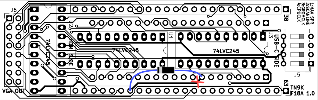
The image earlier in this thread is a little unclear and appears to have the diode the wrong way around.
The image earlier in this thread is a little unclear and appears to have the diode the wrong way around.